Aerodynamic model for HAWT
The aerodynamic part of HAWC2 is based on the principle blade element momentum theory (BEM). The classic approach is though modified to include wake expansion and swirl. Furthermore the BEM is extended with models to handle:
- Dynamic inflow
- Skew inflow
- Shear effect on induction
- Effect from large blade deflections
- Tip loss
- Three dynamic stall models:
- Stig Øye model
- Modified Beddoes-leishmann model
- ATEFlap dynamic stall model that includes the effects of active trailing edge flap deflection
Dynamic inflow:
Dynamic inflow is a general term for the phenomena occurring when the load is changing on the rotor. If the changes are slow the induced velocity is equilibrium with the aerodynamic forces. But if the load changes are fast as e.g. a step change it will take some time before the induction correspond to the quasi steady value.
Skew inflow:
The classical blade element momentum theory was originally designed for axisymmetric flow. Often, however, wind turbines operate at yaw angles relative to the incoming wind, which produces a skewed wake behind the rotor. Therefore a correction is implemented to account for the skewed wake effect.
Shear effect on induction
The BEM part of HAWC2 is based on calculation of thrust and corresponding induction in a polar grid. The thrust in a local grid point is obtained by calculating the thrust using the local grid wind speed, local grid induced velocity at the position of the two neighbouring blades at same radial distance. Afterwards a linear interpolation of Ct on the two blades based on the azimuth distance between grid point and the two blades is used.
Effect from large blade deflections
Large flapwise blade deflections will cause a change in the effective rotor diameter, and blade forces will no longer be perpendicular to the rotor plane. This reduces the thrust on the rotor and is thereby changing the induced velocities and vice versa.
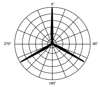
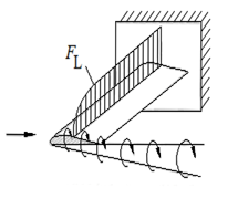
Tip loss
The tip loss correction accounts for the infinite number of blades as assumed in traditional BEM theory. In the tip of the blade the pressure differential between the top and the bottom blade is reduced because the air can travel from the low high pressure at the bottom side of the blade to the top around the end to the low pressure at the top. This effect reduces the lift force in the tip of the blades.
Dynamic stall
Under normal conditions coefficients obtained from wind tunnel tests are sufficient to describe the characteristic of an airfoil. However when the angle of attack is changed rapidly a non-linear effect called dynamic stall occurs. This means that the stall phenomenon does not happen instantaneous but it takes some time for the flow to approach the stationary flow pattern. Two dynamic stall models have been implemented. The first one is generally known as the Øye model, which includes the effect of stall separation lag. The second model is a modified Beddoes-Leishmann model, which includes the effects of shed vorticity from the trailing edge (Theodorsen Theory), as well as the effects of stall separation lag caused by an instationary trailing edge separation point, influencing both lift, drag and pitch moment coefficients. These effects are especially important related to flutter analysis, but also generally to calculate loads and stability of blades with very low torsion stiffness. The ATEFlap dynamic stall model computes the unsteady lift, drag and moment on a 2D airfoil section equipped with Adaptive Trailing Edge Flap. The model captures the unsteady response related to the effects of the vorticity shed into the wake, and the dynamics of flow separation; a thin-airfoil potential flow model is merged with a dynamic
stall model of the Beddoes-Leishmann type.
Near wake model
The near wake model implementation in HAWC2 couples the lifting line theory based near wake model for trailed vorticity with the modified HAWC2 BEM as a far wake model. Inherently included in the trailed vorticity computations are the influences of the tip and root vortices; a ‘root-loss’ model is otherwise not included in HAWC2. The model is described in [1,2] and has been shown to improve the dynamic blade loading in the presence of turbulence, blade vibrations and flap actuations.
In case of strong load gradients on the blade due to for example flaps at fixed angle or other aerodynamic devices activating the near wake model leads to an improved steady state load distribution. When used in this case with a prescribed point distribution along the blade (defined in the ae-file) then sudden changes in the point density (for example close to the flap) should be avoided as they can lead to numerical instability of the model. As with any vortex model, care should be taken when operating in deep stall conditions, such as extreme yaw conditions in standstill.
Current development focuses on the aerodynamic load on swept and pre-bent/deflected blades [3].
[1] Pirrung, G. R., Riziotis, V., Madsen, H. Aa., Hansen, M. H., and Kim, T.: Comparison of a coupled near- and far-wake model with a free-wake vortex code, Wind Energ. Sci., 2, 15-33, https: //doi.org/10.5194/wes-2-15-2017, 2017.
[2] Pirrung, G. R., Madsen, H. Aa., Kim, T., and Heinz, J.: A coupled near and far wake model for wind turbine aerodynamics, Wind Energy, doi:10.1002/we.1969, 2016.
[3] Li, A., Pirrung, G. R., Madsen, H. Aa., Gaunaa, M. and Zahle, F.: Fast trailed and bound vorticity modeling of swept wind turbine blades, J. Phys.: Conf. Ser.1037 062012,https://doi.org/10.1088/1742-6596/1037/6/062012 , 2018.
Aerodynamic model for VAWT
The aerodynamic problem for vertical axis wind turbines is quite complex and different of a horizontal axis wind turbine. This is traditionally handled using double stream tube momentum modeling or using more complex aerodynamic methods like vortex and CFD simulation, whereas the latter are very computationally demanding.
The aerodynamic model for VAWT in HAWC2 is implemented by condensing the three dimensional VAWT to a number of 2D cylinders stacked vertically also called the 2D actuator cylinder model. For the 2D case it is possible to find the steady state solution in a fairly easy way using a modified linear solution of the actuator cylinder approach. The benefit of this is that it is a more physical correct solution than the double stream tube method and a very computational efficient and fast approach compared to vortex and full CFD solutions. The model is extended from a quasi-steady approach with a dynamic inflow model approach known from dynamic BEM formulations of HAWT simulations. Improvement of this model approach is still yet to be done, especially regarding finding the right time constants.